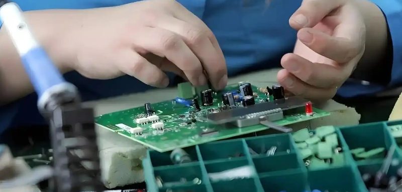
Surface-Mount Technology (SMT) is the backbone of modern electronic manufacturing. Used to assemble components onto printed circuit boards (PCBs), SMT offers faster, more compact, and efficient production than older methods like through-hole technology. In this guide, we’ll walk you through the 8 key steps of the SMT process, from preparation to final inspection, and explain why each stage is crucial for ensuring high-quality PCB assemblies.
Step 1: Preparation: Generating SMT Coordinate Files
The first step in the SMT process involves preparing the PCB layout and Bill of Materials (BOM) for production. Using these inputs, SMT coordinate files are created to guide the placement of components on the board.
Key Preparation Features:
- Surface Identification: The system intelligently distinguishes between the A and B surfaces of the PCB.
- Automatic Correction: Coordinates, angles, and board size are automatically corrected to prevent placement errors.
- Mark Point & Package Verification: The system checks that the correct components match the corresponding pads.
Ensuring that all components are correctly placed is critical for preventing costly mistakes during production.
Step 2: Laser Steel Mesh: Precision Stencil Creation
Once the preparation is complete, a steel mesh stencil is created based on the PCB’s pad layer. The openings in the mesh align perfectly with the PCB pads, ensuring precise solder paste application.
Why This Matters: Accurate solder paste application is vital for the subsequent placement and soldering of components. Poor stencil creation can lead to defective solder joints, which can cause short circuits or weak connections.
Step 3: Solder Paste Printing: Ensuring Precision
With the stencil in place, solder paste is applied to the PCB using a process known as solder paste printing. The paste should be evenly distributed with consistent thickness to ensure that each component can be properly soldered in the next steps.
Quality Control Considerations:
- Uniform Thickness: A consistent paste layer prevents the risk of insufficient or excessive solder, which can lead to defects.
- Accurate Printing: Ensuring that paste is applied only to the pads prevents solder bridges, which can cause short circuits.
Step 4: SPI Detection: Verifying Solder Paste Quality
After solder paste is applied, the next step is Solder Paste Inspection (SPI). SPI uses optical imaging to measure the thickness, area, volume, and height of the solder paste.
What SPI Detects:
- Offset: Misalignment between the stencil and PCB pad.
- Height & Volume: Ensures the paste isn’t too thin or too thick, both of which can cause issues in the reflow process.
- Short Circuits: Identifies potential issues before they become problems.
Using SPI, manufacturers can catch issues early, ensuring only quality PCBs move to the next phase.
Step 5: Component Placement: Precision in Action
In this step, pick-and-place machines position each component onto the PCB pads. These automated machines are fast and highly accurate, picking components from reels or trays and placing them on the board according to the SMT coordinate files.
Why It’s Important: Component placement accuracy is key to ensuring that components fit and function properly once the board is soldered. Misalignment can lead to poor connections or failed circuits.
Step 6: Reflow soldering: Solid Connections
Once components are placed, the PCB is passed through the reflow oven, where the solder paste melts to form permanent solder joints.
The Reflow Process Includes:
- Heating Curve: The temperature curve is carefully controlled to heat the solder paste in three phases: preheating, soaking, and reflow.
- Solidification: As the PCB cools, the solder solidifies, creating strong electrical connections.
Reflow soldering ensures that all components are securely attached to the PCB and electrically connected.
Step 7: AOI inspection: Visual Quality Control
After reflow soldering, Automated Optical Inspection (AOI) is used to visually inspect the board. AOI machines capture high-resolution images of the PCB and compare them to a reference image to identify any defects.
AOI Checks Include:
- Component Placement: Verifying that components are correctly oriented and aligned.
- Solder Joint Quality: Ensuring that solder joints are smooth, uniform, and free of defects such as cold solder joints or solder bridges.
- Missing or Misplaced Components: Detecting any issues where a component might have been left out or misaligned.
This step ensures that only fully functional boards proceed to the next stage.
Step 8: Xray inspection: Detecting Hidden Defects
For more complex boards, especially those with Ball Grid Arrays (BGAs), X-ray inspection is used. X-ray machines can see through components and check solder joints that are hidden beneath the package.
What X-Ray Inspection Detects:
- BGA Soldering Issues: Checks for tin connections, short circuits, or voids under BGAs.
- Hidden Solder Bridges: Detects faults that can’t be seen through AOI.
- Lack of Solder or Voids: Identifies insufficient solder or voids, which could compromise the electrical connection.
X-ray inspection is critical for ensuring that no defects are hidden beneath complex components.
Conclusion: The Critical Role of SMT in Modern Electronics
SMT has become an essential part of modern PCB assembly, allowing manufacturers to produce smaller, faster, and more reliable electronic devices. By following these eight key steps, from preparation to final inspection, manufacturers can ensure high-quality products that meet industry standards.
Greens Technology provide the serivces including pcb fabrication and layout, components sourcing, the SMD assembly and through hole assemby , FCT testing and turnkey assembky , package and delivery.
If you have any projects need prices checking, please send the gerber files and BOM list to us. We will provide the competitive quote within 3 days.
Email:sales@greenspcba.com
